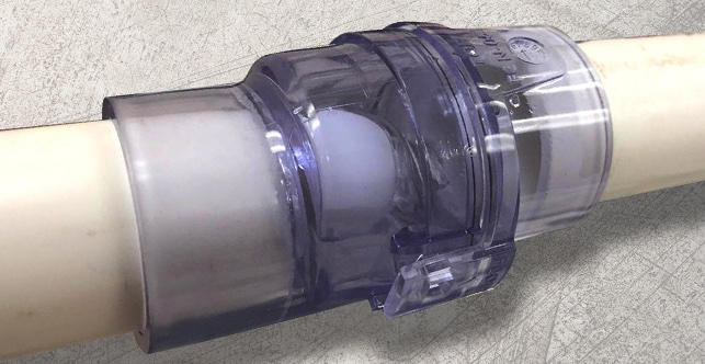
The Air-Trap allows liquid condensate to drain from the HVAC equipment and simultaneously prevents air from entering or escaping from the equipment.
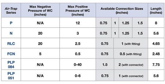
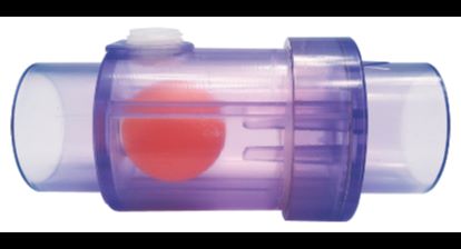
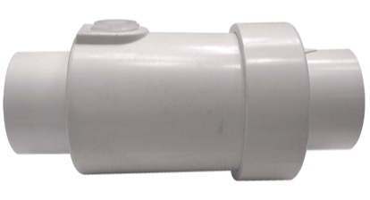
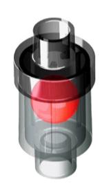
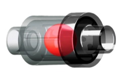
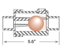
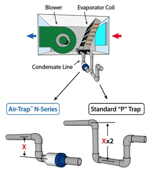
Figure 1 (right): Shows for a standard “P” Trap the vertical distance required between center lines of unit connection and the center line of the bottom of the trap is 4 inches when there is a 2-inch negative plenum pressure. By comparison, the Air-Trap N-Series is only 2 inches, not the 4 inches required with the standard “P” trap.
Why a Waterless Trap?
Patented: US9777957B1
Typically, HVAC equipment is fitted with “P” traps that require water, or another liquid, within a standpipe to prevent gas from entering or leaving the unit. As a result, the “P” traps are susceptible to freezing - expansion - bursting. At other times, the traps dry out allowing gas to escape or enter the HVAC equipment. The Air-Trap™ never requires addition of water to prevent unwanted air leakage.
The Air-Trap reduces trap height by up to 60%. A total height equal to the maximum water pressure in inches WC. With negative pressure plenum, the HVAC Air-Trap requires less than ½ the height required for P‑Trap installation.
N-Series in Operation
A video highlighting the operation of the N-Series installed in a negative pressure orientation.
N-Series Negative Orientation Animation
An animation detailing N-Series concept for a negative pressure installation.
N-Series Positive Orientation Animation
An animation detailing N-Series concept for a positive pressure installation.
Note: The attached drawings represent traps that operate under negative pressure. Never connect condensate drain directly to a sanitary drain line.
Figure 1: Trap Required in Condensate Line
If the condensate drain line is under negative pressure (e.g., upstream of blower as shown here) a trap is required
N-Series
¾" 1" 1¼" 1½" Clear
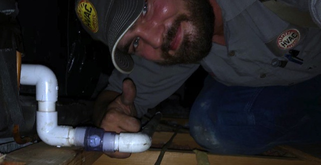
N-Series Videos
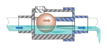
Figure 2: When condensation is not present, the negative pressure within the plenum draws the internal mechanism against the valve seat preventing air from entering the AHU through the drainpipe.
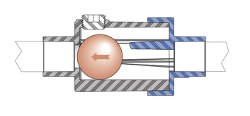
Figure 3: As condensate forms, water builds up in the vertical pipe. When the water pressure equals the negative air pressure in inches of water column, the force of the water head becomes equal or greater than the negative pressure — the internal mechanism moves to the right, and water flows.
Figure 4: When there is no longer a requirement to remove condensation, the negative pressure returns the ball to the valve seat and prevents airflow to the unit plenum. The internal rails aid in returning the ball to the seat in case the variable speed fan is operating at a low flow and low negative pressure.

For Use as Negative / Positive Pressure Waterless Trap
Maximum Pressures, Connection Sizes & Length
Click below button to see available sales locations and distributors
or purchase the N-Series below using the secure checkout from our Shopify store, waterless-trap.com
HVAC Air-Trap
• Operates Dry — Eliminating:
- Freezing and breaking
- Dryouts
- Sludge buildup
- Geyser effect
- Mold and mildew caused by geyser effect
• Prevents air leakage
• Reduces trap height requirement by 1/2
• Predesigned — eliminating field-designed errors
No More Troublesome "P" Traps
Negative Pressure Orientation
Positive Pressure Orientation
Benefits
• Reduces sludge buildup that normally accumulates in standard “P” trap
• Prevents water blow out when condensate begins to form at the beginning of cooling season when trap has dried and air is rushing into HVAC unit plenum, causing water spray into fan plenum compartment
• Since there is no water in the trap, there is no chance of freezing during cold periods.
• Reduces the trap height by approximately 50% as compared to the “P” trap
Features
• Schedule 40 PVC with clean out port
• Retains no water after condensing has ceased
• Meets general building codes.
Specifications
Maximum negative pressure of WC: 20"
Maximum positive pressure of WC: 3"
Maximum Condensate Flow, GPM (all connection sizes):
Any Negative Pressure:
2.0
Positive Pressure:
0.06 at 5" WC
0.19 at 4" WC
0.21 at 3" WC
0.21 at 2" WC
Length: 5.6"
Flammability rating is UL94 V-0
Air-Traps Meet IMC® Code Section M307.2.4.1
N-Series Operation
Available Models and Connection Sizes
¾" 1" 1¼" 1½" White
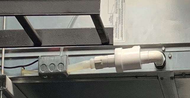
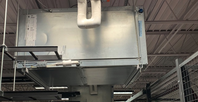
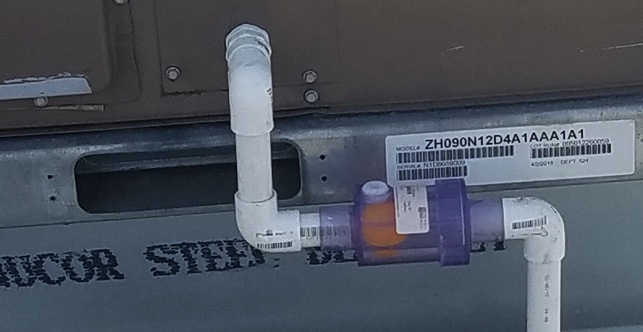
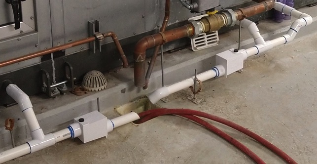
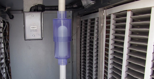
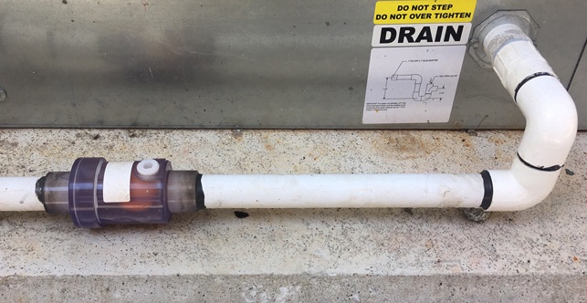
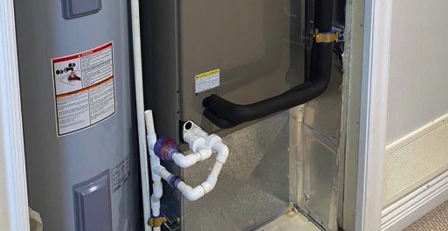
N-Series Installations
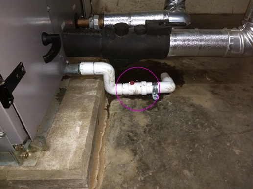
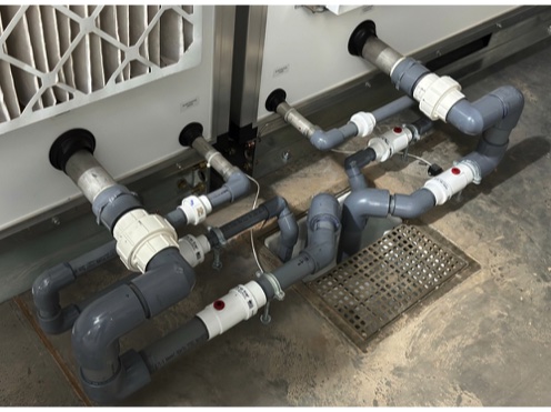
N-Series, commercial mechanical room negative pressure installation.
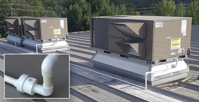
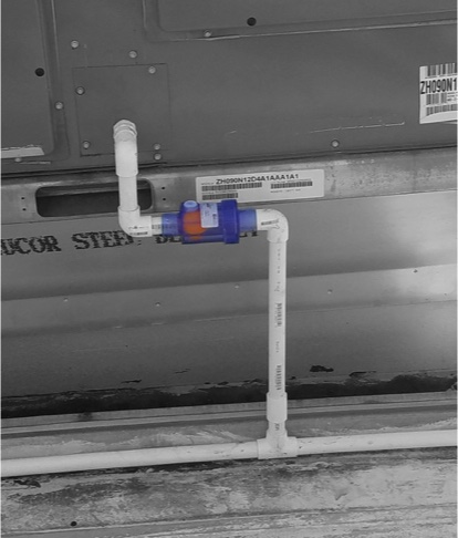
N-Series commercial rooftop negative pressure installation.
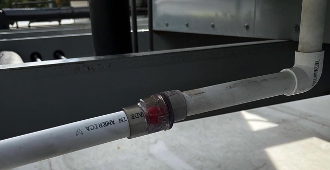
Multiple N-Series and Union Strainers installed at a data center in Brazil. The N-Series Air-Trap is specified.