The Air-Trap allows liquid condensate to drain from the HVAC equipment and simultaneously prevents air from entering or escaping from the equipment.
P-Series in Operation
A video highlighting the operation of the P-Series installed in a positive pressure orientation.
P-Series Positive Orientation Animation
An animation detailing P-Series concept for a positive pressure installation.
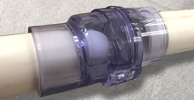
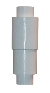
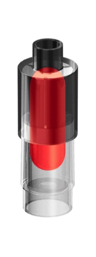
¾" 1" 1¼" 1½" Clear
Why a Waterless Trap?
Note: The attached drawings represent traps that operate under positive pressure. Never connect condensate drain directly to a sanitary drain line.
Typically, HVAC equipment is fitted with “P” traps that require water, or another liquid, within a standpipe to prevent gas from entering or leaving the unit. As a result, the “P” traps are susceptible to freezing - expansion - bursting. At other times, the traps dry out allowing gas to escape or enter the HVAC equipment. The Air-Trap never requires addition of water to prevent unwanted air leakage.
• The Air-Trap allows water to drain from the HVAC equipment.
• Prevents air from entering or escaping from the equipment.
• The Air-Trap operates dry when no water removal is required and wet when it is required.
P-Series
P-Series Videos
Positive Pressure Waterless Trap
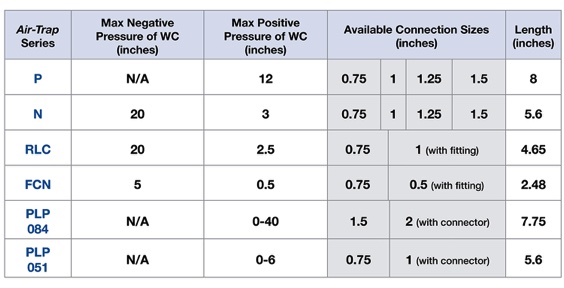
Maximum Pressures, Connection Sizes & Length
Click below button to see available sales locations and distributors
or purchase the P-Series below using the secure checkout from our Shopify store, waterless-trap.com
HVAC Air-Trap
• Operates Dry — Eliminating:
- Freezing and breaking
- Dryouts
- Sludge buildup
- Geyser effect
- Mold and mildew caused by geyser effect
• Prevents air leakage
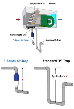
• Reduces trap height requirement by 1/2
• Predesigned — eliminating field-designed errors
No More Troublesome "P" Traps
Positive Pressure Orientation
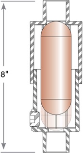
P-Series Operation
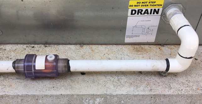
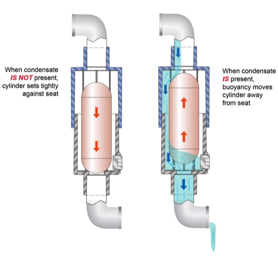
• P-Series Air-Trap requires no water head to cause the trap to operate. Simply come out of the plenum condensate line and go down into the P-Series Air-Trap. Come out of the trap and go horizontally with your drain line. The height requirement then becomes the height of the trap plus two elbows.
• When removing water, the water exits the unit but no air escapes the unit.
• Reduces sludge buildup that normally accumulates in standard “P” traps.
• Prevents problem with standard “P” trap never filling with water when condensate begins to form at the beginning of the cooling season.
• Prevents freezing of trap during cold periods since there is no water in the trap.
Features
• Schedule 40 PVC with clean out port
• Retains no water after condensing has ceased
• Requires no water head to cause trap to operate
• Meets general building codes. For use on HVAC equipment only. Not for use as a sanitary trap.
Specifications
Maximum negative pressure of WC N/A
Maximum positive pressure of WC 12"
Maximum Condensate Flow, GPM (all connection sizes):
Any Negative Pressure:
N/A
Positive Pressure:
0.5 at 12" WC
1.0 at 8" WC
1.5 at 7" WC
2.0 at 4" WC
Length 8"
Flammability rating is UL94 V-0
Air-Traps Meet IMC® Code Section M307.2.4.1
Available Models and Connection Sizes
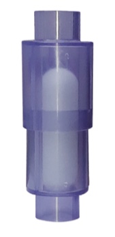
¾" 1" 1¼" 1½" White
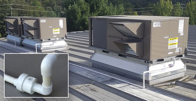
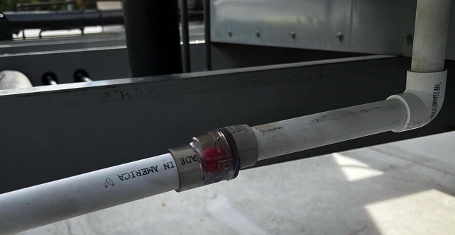
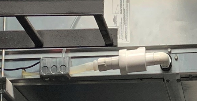
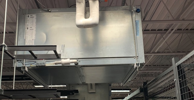
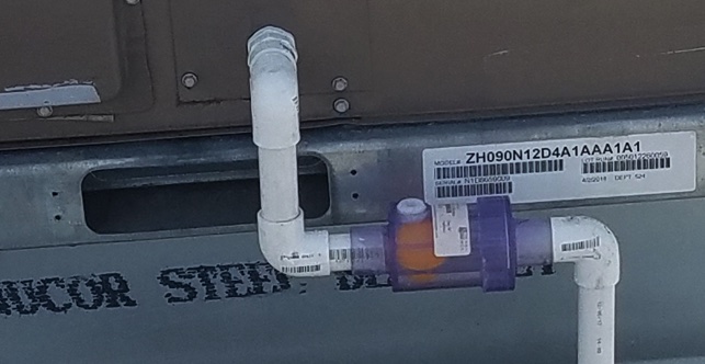
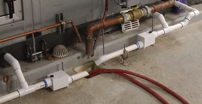
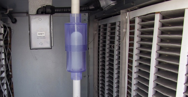
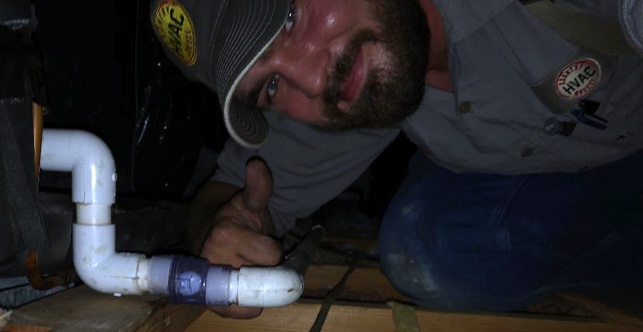
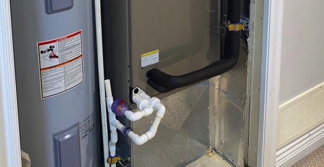
P-Series Installations
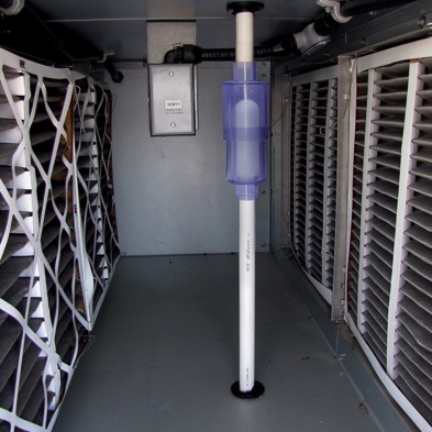
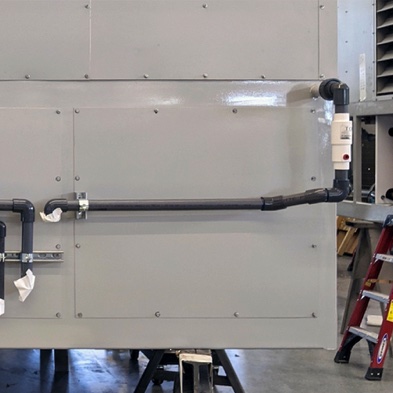
P-Series commercial positive pressure internal installation.
P-Series commercial positive pressure installation directly into schedule 80 PVC.
Patented: US9777957B1